
How Does a BMS Manage Multiple Battery Packs Connected in Parallel?
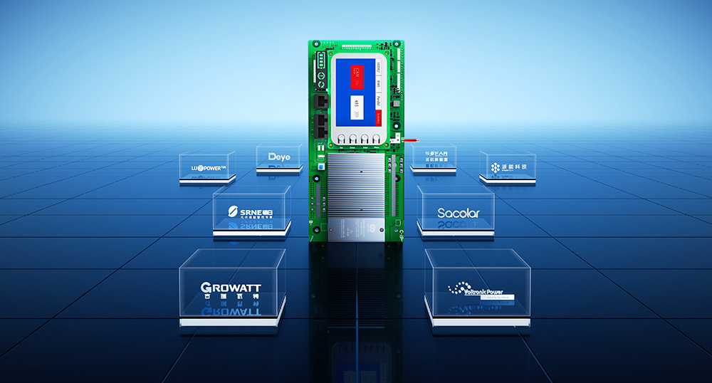
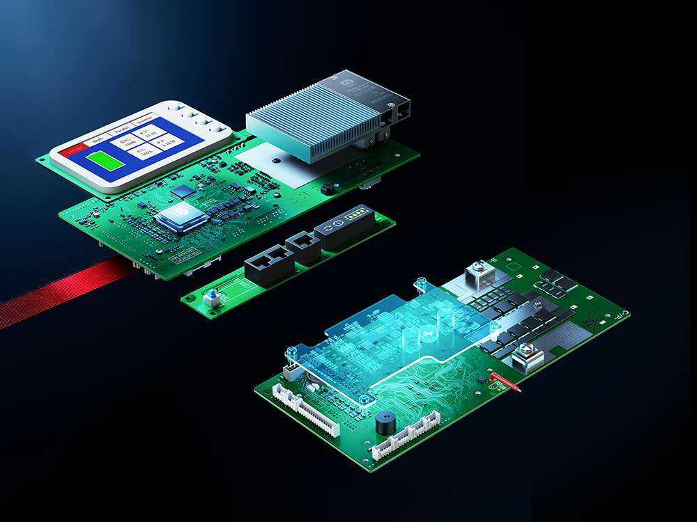
The DALY 4th Generation Home Energy Storage BMS is designed for lithium battery applications, offering multiple model configurations to support different electrical requirements and system integration
Connecting multiple battery packs in parallel is one way to expand the capacity of a battery energy storage system while maintaining the same nominal voltage. However, a multi-pack system requires more than connecting the positive and negative terminals of several batteries.

Each battery pack has its own electrical characteristics and operating condition. The system design must account for current distribution, overcurrent protection, wiring, battery compatibility, and communication requirements.
For a system using multiple independently managed battery packs, the Battery Management System (BMS) plays an important role in monitoring and protecting each pack. Where the system uses inter-pack communication, the communication architecture must also be configured correctly.
This article explains the main design considerations for parallel battery packs and distinguishes general engineering principles from the confirmed parallel specifications of DALY’s fourth-generation home energy storage BMS models.
1. What Happens When Battery Packs Are Connected in Parallel?
When battery packs with compatible nominal voltage are connected in parallel, the system voltage remains at the same nominal level while the available capacity can increase.
For example, connecting two compatible 51.2V, 100Ah battery packs in parallel gives a nominal system voltage of 51.2V and a combined nominal capacity of 200Ah.
This is a simplified capacity example. It does not establish that any two battery packs can be connected together. The battery manufacturer’s instructions, pack voltage, state of charge, chemistry, series configuration, current limits, protection devices, and system wiring must all be checked.
Parallel connection can be used to expand an energy storage installation, but the permitted number of packs and the system’s available current depend on the specific battery, BMS, wiring, and system design.
What needs to be checked before connecting packs?
Before connecting battery packs in parallel, verify:
– The battery chemistry and series configuration are compatible.
– The pack voltage and state of charge are within the manufacturer’s permitted connection conditions.
– The battery packs are in an acceptable condition.
– Each pack has appropriate protection.
– The cables, busbars, connectors, fuses, and disconnect devices are correctly rated.
– The BMS supports the intended parallel architecture.
– Communication wiring and addressing follow the product instructions, where inter-pack communication is required.
Do not use a general rule from one battery manufacturer as a universal installation instruction for another battery system.
2. Why Does Each Battery Pack Need Its Own BMS?
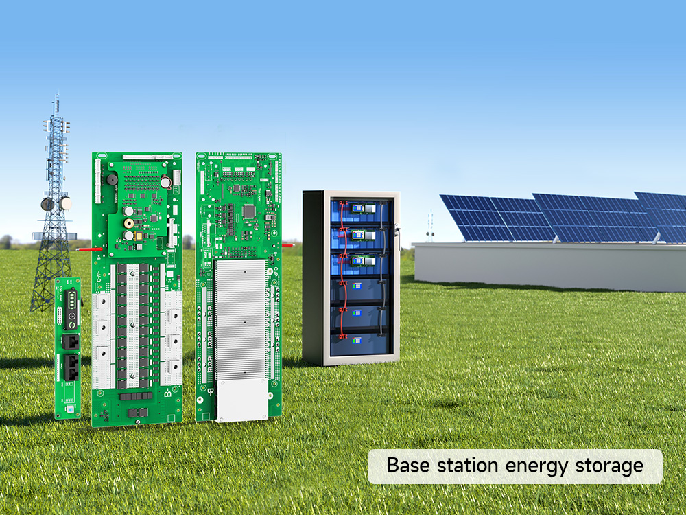
In a multi-pack architecture where each battery pack is independently managed, each pack has its own BMS.
The BMS monitors the cells within its associated pack and applies the protection and control functions provided by that product. This allows the condition of each pack to be managed at pack level rather than treating all cells in the installation as one undifferentiated group.
A typical independently managed pack includes:
– Battery cells connected in the required series configuration
– A BMS protection board
– Cell-voltage sampling connections
– Temperature sensors, where included in the design
– Power connections
– Communication connections, where required by the system architecture
The exact components and wiring depend on the battery and BMS design. Follow the relevant product manual and approved system diagram.
What does the BMS do in a parallel battery system?
Depending on the BMS design, its functions may include:
– Monitoring cell voltages within the pack
– Monitoring battery current and temperature
– Applying configured charge and discharge protection
– Reporting pack operating information
– Communicating with other BMS units or an external controller, where supported
A BMS installed in each pack does not remove the need for system-level protection. The complete installation still requires appropriate cables, fuses, disconnect devices, and an engineered protection strategy.
3. How Do Multiple BMS Units Communicate?
Some multi-pack systems use communication between the BMS units so that pack information can be exchanged or coordinated.
The communication arrangement depends on the product architecture. A common arrangement uses a designated master pack and other packs connected as subordinate units. The exact roles, data exchanged, and control behavior must be defined by the BMS manufacturer.
Master and subordinate packs
In a master/subordinate architecture:
– The master BMS acts as the designated communication point for the system or external equipment, according to the product design.
– Subordinate BMS units provide their pack information through the inter-pack communication network.
– The system uses the communication arrangement and addressing method specified for the product.
The terms “master” and “subordinate” describe communication roles. They do not mean that the master pack replaces the individual protection functions of the other BMS units.
Do not assume that every BMS parallel system uses a master/subordinate architecture. Confirm the architecture in the applicable product documentation.
RS485 daisy-chain communication
RS485 is an electrical interface standard commonly used for serial communication. A daisy-chain arrangement connects devices sequentially along a communication path.
In a product-specific RS485 daisy-chain design, the inter-pack communication cables are connected in the order and through the ports specified by the manufacturer. Addressing is used to distinguish the connected BMS units where the system requires individual device identification.
Important installation checks include:
– Use the specified communication cable and pinout.
– Connect the designated ports in the required sequence.
– Configure or verify device addresses as instructed.
– Follow the manufacturer’s requirements for cable length, termination, grounding, and routing.
– Do not assume that the RJ45 connector means the connection is Ethernet. RJ45 describes the connector form; the electrical interface and protocol depend on the product.
RS485 alone does not define the application-level data protocol. Devices also need compatible communication settings and message definitions.
4. What Is Parallel Current Limiting?
When two battery packs at different voltages are connected in parallel, a current can flow between them as they move toward a common voltage. The magnitude of this current depends on factors including the voltage difference and the resistance of the complete connection path.
A BMS product may include a parallel current-limiting function to control current associated with pack connection or parallel operation. The exact function, operating sequence, and limits depend on the circuit design and product specification.
Peak and continuous parallel current limiting are different values
These two specifications should not be confused:
– **Peak parallel current limiting** is a peak value associated with the specified parallel current-limiting function.
– **Continuous parallel current limiting** is the separately specified continuous value for that function.
Neither value should be confused with the BMS’s main continuous charge/discharge current rating.
A peak value must not be interpreted as a continuous operating current. The permitted duration, trigger conditions, response time, and test conditions should only be stated if the product documentation provides them.
What should an engineer verify?
For the exact BMS model, check:
– Peak parallel current-limiting value
– Continuous parallel current-limiting value
– Whether the value applies to pack connection, ongoing parallel operation, or another defined operating condition
– Trigger conditions and voltage-difference limits, if specified
– Response time and permitted peak duration, if specified
– Required wiring and interface board
– Maximum supported number of parallel packs
If the product documentation does not state a test condition or response time, do not estimate or invent one.
5. How Many Battery Packs Can Be Connected in Parallel?
There is no single maximum number that applies to all BMS products. The supported number depends on the model, hardware architecture, communication design, protection function, and approved system configuration.
A maximum pack count stated for one BMS model must not be transferred to another model merely because both belong to the same product family.
Confirmed DALY fourth-generation home energy storage BMS information
The following values reflect the latest DALY product facts confirmed for this article. They must be checked against the current controlled selection table before publication.
| Model | Peak parallel current limiting | Continuous parallel current limiting | Confirmed maximum parallel packs |
|—|—:|—:|—:|
| R16LK | 10A | 2A | Up to 16 |
| R16LM-B | 10A | 3A | Up to 16 |
| R16LS-A | 20A | Not stated in the confirmed information used here | Up to 63 |
| R16LS-B | 5A | Not stated in the confirmed information used here | Not confirmed |
**Important:** The absence of a value in this table means that the information has not been confirmed for this article. It must not be interpreted as zero or as evidence that the function is unavailable.
R16LS-A: 20A peak parallel current limiting and up to 63 packs
The latest confirmed product information for DALY R16LS-A specifies:
– 20A peak parallel current limiting
– Support for up to 63 battery packs in parallel
These are model-specific product facts. They should not be generalized to R16LK, R16LM-B, R16LS-B, or other DALY product families.
The 63-pack figure is a stated product parallel-pack capability. It does not, by itself, define the complete installation design, cable arrangement, communication distance, refresh interval, monitoring interface, or commissioning procedure for a 63-pack system.
Those details must follow the applicable product documentation and system engineering requirements.
Do not confuse system parallel capacity with display capacity
A local display’s ability to show a certain number of pack records is a user-interface specification. It is not automatically the same as the BMS system’s maximum electrical or communication parallel capacity.
For example, the confirmed information provided for the fourth-generation system distinguishes the R16LS-A system capability of up to 63 packs from a 3.5-inch display’s parallel page, which displays up to 16 groups.
The display limit must not be presented as the system’s maximum parallel-pack count. Likewise, the 63-pack system capability must not be used to claim that a particular display shows all 63 packs simultaneously.
6. How Is a Large Parallel System Addressed?
When a system contains multiple BMS units, each unit may need an address so that it can be identified on the communication network.
The addressing method depends on the product. Some systems use manual address configuration; others provide automatic addressing or a combination of methods.
For the DALY fourth-generation models, the confirmed information is model-specific:
– **R16LK and R16LM-B:** automatic BMS address identification is confirmed in the available product information.
– **R16LS-A:** the supplied product information describes automatic and manual coding modes and a six-position DIP switch on the interface board.
– **R16LS-B:** do not assume the same addressing method without model-specific confirmation.
A six-position DIP switch provides a physical coding arrangement. It should not be described as proof of a particular network topology, ring redundancy, communication protocol behavior, or automatic discovery procedure unless the product documentation explicitly confirms those details.
For installation, use the addressing procedure and port sequence in the manual for the exact model and interface board.
7. What Communication Details Should Be Confirmed for 17–63 Packs?
A product’s stated maximum parallel-pack count does not automatically provide every engineering detail required for a large installation.
For a system with more than 16 packs, the project team should confirm the following information from the applicable product documents or DALY technical team:
| Item | What needs to be confirmed |
|—|—|
| Communication topology | Exact connection sequence and whether any special branching or termination is required |
| Addressing | Automatic/manual addressing method and address allocation procedure |
| Maximum cable distance | Permitted cable length for the specified communication arrangement |
| Data refresh interval | Update rate for pack data and system-level data |
| Fault handling | Behavior when a BMS loses communication or reports a fault |
| Monitoring | Which interfaces and platforms can display individual pack data and system summaries |
| Display capacity | Number of packs that can be displayed and how pages or groups are presented |
| Commissioning | Required checks before the packs are placed into operation |
Do not state a maximum communication distance, refresh interval, or fault-response time unless it is supported by a model-specific technical document.
APP and cloud monitoring
Monitoring through an APP or cloud platform is separate from the electrical parallel capability.
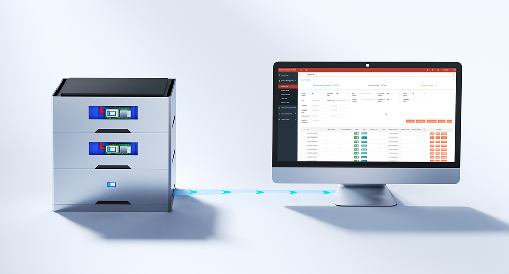
If a BMS configuration supports Bluetooth, WiFi, 4G, or a cloud platform, confirm which hardware accessories and network connection are required. Also verify whether the platform can display data from every pack in the intended system size.
Do not claim that a 17–63-pack system automatically provides a consolidated cloud report unless the relevant platform documentation demonstrates that function.
8. Parallel Battery System Design: Practical Checks
A multi-pack installation should be designed as a complete electrical system. Battery current does not necessarily divide equally among packs simply because they are connected in parallel. Cable resistance, connection layout, pack voltage, battery characteristics, and operating conditions can affect current distribution.
Battery manufacturers publish model-specific installation requirements. For example, Victron’s battery installation guidance describes individual battery fusing and cable arrangements intended to provide more equal current paths for the specific products covered by that guide. These instructions are useful as an example of why wiring design matters, but they must not be treated as universal instructions for every battery product.
Before commissioning a parallel battery bank, check:
1. Pack compatibility and permitted connection conditions.
2. Individual pack protection and the main battery-bank protection.
3. Cable and busbar sizing.
4. Current paths and connection layout.
5. BMS communication wiring and addressing.
6. Inverter communication and system settings.
7. Manufacturer commissioning procedure.
8. Fault isolation and maintenance access.
The final wiring and protection design should be based on the battery and BMS manufacturer’s instructions and the applicable electrical requirements in the installation location.
Conclusion: Confirm the Parallel Architecture Before Expanding the Battery System
Connecting multiple battery packs in parallel can increase the capacity of a home energy storage installation, but the design must account for more than the number of packs.
Each independently managed pack needs the protection and monitoring arrangement specified for the system. Where the BMS units communicate with each other, the communication topology, addressing method, and external inverter connection must follow the product design.
DALY’s fourth-generation home energy storage models have different confirmed parallel specifications. R16LK and R16LM-B support up to 16 packs, while R16LS-A is specified for up to 63 packs with 20A peak parallel current limiting. The R16LS-B parallel-pack maximum should be confirmed separately.
The correct configuration depends on the exact BMS model, battery packs, wiring, communication requirements, and installation design.
Request a Parallel-System Configuration Review
Planning a multi-pack home energy storage system?
Prepare the following information before requesting a technical review:
– BMS model and current rating
– Battery chemistry and series configuration
– Battery capacity and pack voltage
– Planned number of parallel packs
– Inverter manufacturer and exact model
– Required CAN or RS485 communication
– Display and monitoring requirements
– Available wiring diagram or system layout
Providing these details helps the technical team review the applicable BMS configuration and identify which product specifications and installation requirements need to be checked.
—
3. FAQ
Q1. Does each battery pack need its own BMS in a multi-pack system?
In an architecture where each pack is independently managed, each pack has its own BMS. The exact protection and communication arrangement depends on the battery system design and the manufacturer’s instructions.
Q2. What is the difference between a master BMS and a subordinate BMS?
These terms describe communication roles in a master/subordinate architecture. The master is the designated communication point for the system or external equipment, while subordinate units provide their pack information through the specified communication network. Each pack’s own BMS protection functions remain subject to its product design.
Q3. What is RS485 daisy-chain communication?
It is a serial communication arrangement in which devices are connected sequentially along a communication path using an RS485 electrical interface. The exact ports, cable, addressing, termination, and wiring sequence must follow the equipment manufacturer’s instructions.
Q4. Does a 20A peak parallel current-limiting value mean the BMS can continuously carry 20A between packs?
No. A peak value and a continuous value describe different specifications. The permitted duration and operating conditions must be taken from the product documentation. Do not treat a peak value as a continuous rating.
Q5. How many battery packs can DALY R16LS-A support in parallel?
The latest confirmed DALY product information used for this article specifies up to 63 packs in parallel and 20A peak parallel current limiting for R16LS-A. The system wiring, communication, commissioning, and other operating conditions must still be verified for the actual project.
Q6. Do R16LK and R16LM-B also support 63 packs in parallel?
No such 63-pack capability is confirmed for these two models in the product facts used here. R16LK and R16LM-B are confirmed for up to 16 packs in parallel. Do not transfer the R16LS-A maximum to other models.
Q7. Does a 3.5-inch display showing 16 packs mean the BMS system supports only 16 packs?
No. Display capacity and system parallel capacity are different specifications. The confirmed R16LS-A system capability is up to 63 packs, while the referenced 3.5-inch display parallel page shows up to 16 groups. Do not assume the display shows all 63 packs simultaneously.
Q8. Can 17–63 packs automatically be monitored together through an APP or cloud platform?
The maximum parallel-pack specification alone does not prove the detailed APP or cloud reporting capability for 17–63 packs. The supported monitoring arrangement and display of individual or aggregated data should be confirmed for the exact hardware, accessories, and platform configuration.
Related products
-

Factory OEM 10 inch large carbon fiber cone woofer subwoofer subwoofer subwoofer speaker home use $72-$79
Contact UsFactory OEM 10 inch big carbon fiber basin woofer speakers super woofer horn super bass loudspeaker subwoofer speaker for home
Factory OEM 10-inch Carbon Fiber Subwoofer (Home Audio) -

Many models 3 4 4 ohm 8 ohm midrange full range bass subwoofer speakers
Contact UsMany 3-inch/3.5-inch speakers
Please click on the image on the left -
PCBA Assembly for Electric Vehicle Charging Infrastructure
Contact UsOur EV Charging Station PCBA is designed for modern electric vehicle charging applications, delivering safe, stable, and durable performance under high current and high-voltage conditions.
-

HAKRC F405 D Mini FC
Contact UsHAKRC F4520D Flight Controller provides great power all in a 20x20mm mounting pattern.
Reviews
There are no reviews yet.